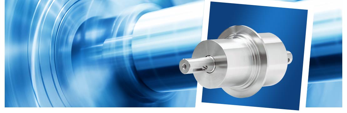
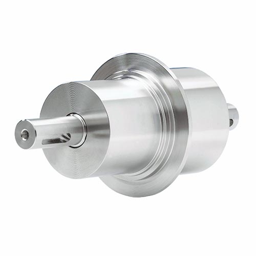
Rotary feedthroughs with KF flange
Low-priced standard models
For high rotational speeds
These rotary feedthroughs are available with the following flanges: KF-DN 25, 32, 40 and 50. They are delivered with a suitable O-ring, which is also available as a spare part. The shaft is connected using parallel keys.
Technical data
Leakage rate: < 1 x 10⁻⁸ mbar x l/sOperating temp., non-cooled: -20 bis 90 °C
Operating temperature, cooled: > 90 °C
Rotational speed: up to 10,000 rpm
Torque: up to 32 Nm
Pressure differential: up to 1 bar
Vacuum range: up to UHV
Shaft diameter: up to 15 mm
Flange diameter: up to 50 mm
Radial load: up to 200 N
Axial load: up to 150 N
Housing: Stainless steel
Shaft: Stainless steel, magnetic
Magnetic fluid: Maintenance-free
Available options
- Housing cooling
- Customer-specific versions
| Model | ALMA-M-KF-008-V-U | |||
|---|---|---|---|---|
| Part number | 1020293 | |||
| Weight (kg) | 0.230 | |||
| Dimensions (mm) | ||||
| Shaft diameter, vacuum side [lg7] | 8.0 | |||
| Shaft diameter, atmospheric side [lg7] | 8.0 | |||
| Shaft length, vacuum side [D] | 36.0 | |||
| Shaft length, atmospheric side [E] | 23.0 | |||
| Total length [A] | 95.0 | |||
| Length, atmospheric side [C+E] | 59.0 | |||
| Length, vacuum side [B+D] | 36.0 | |||
| Total housing length [B+C] | 36.0 | |||
| Housing length, vacuum side [B] | – | |||
| Housing length, atmospheric side [C] | 36.0 | |||
| Housing diameter, vacuum side [L] | – | |||
| Housing diameter, atmospheric side [Kg7] | 28.0 | |||
| Length of parallel-key groove [F] | – | |||
| Distance from parallel-key groove to shaft end [G] | – | |||
| Width of parallel-key groove [HN9] | – | |||
| Flange diameter [KF] | KF-DN 25 | |||
| Shaft specification | ||||
| Max. rotational speed | 10,000 min-1 | |||
| Max. transmittable torque* | 5.00 Nm | |||
| Friction torque | 0.25 Nm | |||
| Max. axial load [Fa1]** | 30.00 N | |||
| Max. axial load [Fa2]** | 30.00 N | |||
| Max. radial load [Fr1]** | 30.00 N | |||
| Max. radial load [Fr2]** | 30.00 N | |||
| ALMA-M-KF-010-V-U | ||||
|---|---|---|---|---|
| 1020294 | ||||
| 0.500 | ||||
| 10.0 | ||||
| 10.0 | ||||
| 30.0 | ||||
| 27.0 | ||||
| 115.0 | ||||
| 65.0 | ||||
| 50.0 | ||||
| 58.0 | ||||
| 20.0 | ||||
| 38.0 | ||||
| 30.0 | ||||
| 38.0 | ||||
| 17.0 | ||||
| 4.0 | ||||
| 3.0 | ||||
| KF-DN 32 | ||||
| 10,000 min-1 | ||||
| 9.00 Nm | ||||
| 0.3 Nm | ||||
| 50.00 N | ||||
| 50.00 N | ||||
| 75.00 N | ||||
| 75.00 N | ||||
| ALMA-M-KF-012-V-U | ||||
|---|---|---|---|---|
| 1020292 | ||||
| 0.850 | ||||
| 12.0 | ||||
| 12.0 | ||||
| 35.0 | ||||
| 30.0 | ||||
| 150.0 | ||||
| 85.0 | ||||
| 65.0 | ||||
| 85.0 | ||||
| 30.0 | ||||
| 55.0 | ||||
| 36.0 | ||||
| 45.0 | ||||
| 20.0 | ||||
| 5.0 | ||||
| 4.0 | ||||
| KF-DN 40 | ||||
| 7,500 min-1 | ||||
| 16.00 Nm | ||||
| 0.3 Nm | ||||
| 50.00 N | ||||
| 50.00 N | ||||
| 75.00 N | ||||
| 75.00 N | ||||
| ALMA-M-KF-015-V-U | ||||
|---|---|---|---|---|
| 1020295 | ||||
| 1.400 | ||||
| 15.0 | ||||
| 15.0 | ||||
| 35.0 | ||||
| 30.0 | ||||
| 160.0 | ||||
| 80.0 | ||||
| 80.0 | ||||
| 90.0 | ||||
| 45.0 | ||||
| 45.0 | ||||
| 49.0 | ||||
| 57.0 | ||||
| 20.0 | ||||
| 5.0 | ||||
| 5.0 | ||||
| KF-DN 50 | ||||
| 9,000 min-1 | ||||
| 32.00 Nm | ||||
| 0.4 Nm | ||||
| 150.00 N | ||||
| 150.00 N | ||||
| 200.00 N | ||||
| 200.00 N | ||||
* The torque calculation is based on mean calculated values.
** The load calculation is based on assumed values, which cover 95 % of applications.
Individual calculations can be made for borderline applications.
** The load calculation is based on assumed values, which cover 95 % of applications.
Individual calculations can be made for borderline applications.

")