Why Torsional Rigidity? The Fundamental Problem:
In a vacuum system, rotary motion is transmitted from outside through a feedthrough to the process side. A coupling connects the drive to the component. If the coupling has low torsional stiffness, it twists under load. The motor angle then no longer matches the component angle, resulting in a loss of positioning accuracy and repeatability.
Angular Backlash = Positioning Error
Even slight torsional deflection can translate into deviations at the sample through gearing and lever arms.
Vibration & Control Loops
Flexible couplings can introduce resonances and destabilise highly dynamic servo control.
No Misalignment Compensation = Bearing Damage
Without misalignment compensation, reaction forces place loads on bearings and the rotary feedthrough, which are difficult to service in a vacuum environment.
What “Torsionally Rigid” Means in Technical Terms
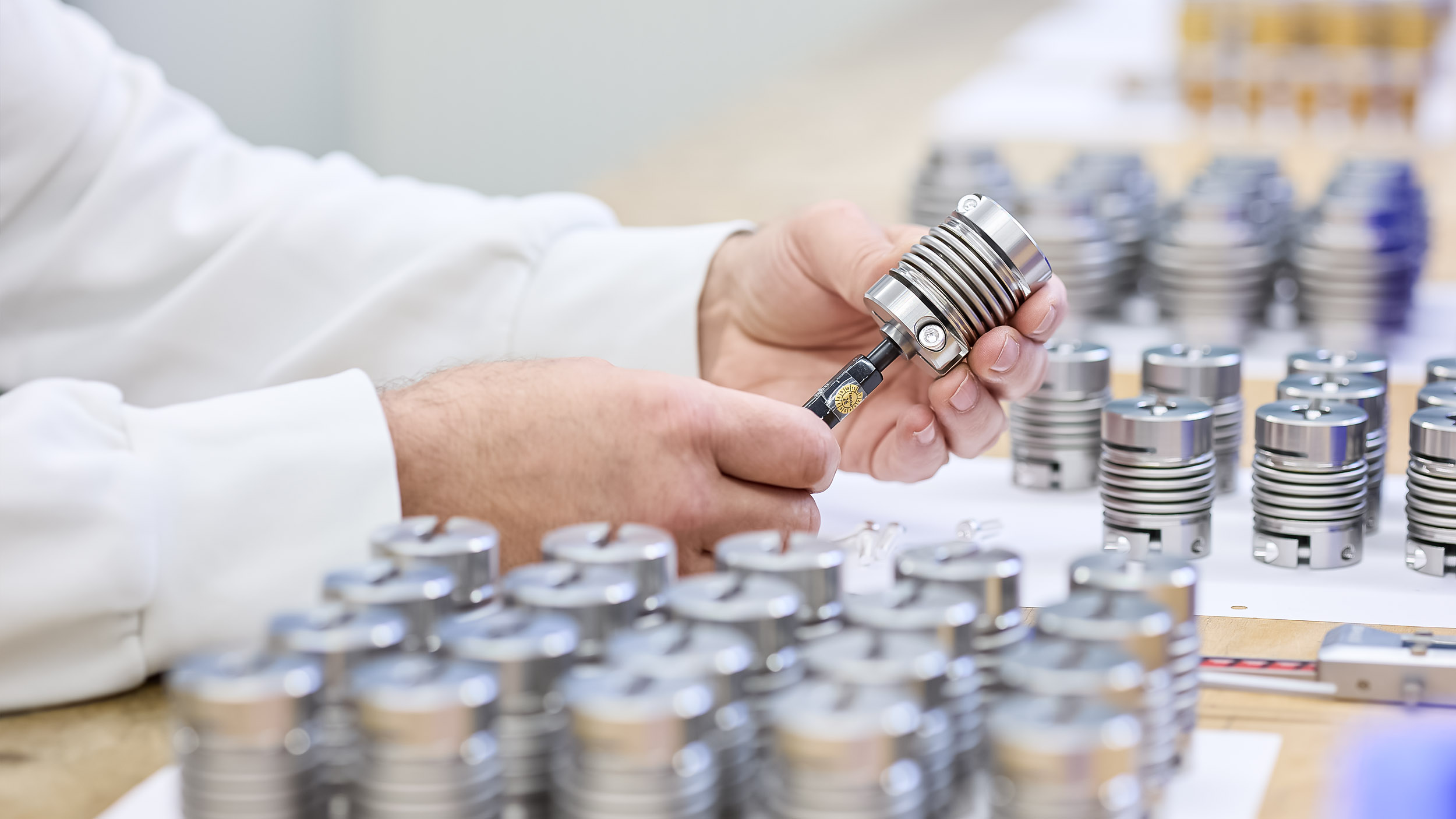
The thin-walled metal bellows transmits torque with virtually no angular backlash. No elastomer, no breakaway play.
The bellows flexes readily in axial, lateral and angular directions, compensating for manufacturing and assembly tolerances.
Clamping hubs or taper clamping create a frictional connection to the shaft, without a key or reversal backlash.
No plastics or lubricants: compatible with HV/UHV environments, bake-out and radiation.
The Intermediate Unit in a Vacuum Drive System
The coupling is the only component that compensates for mechanical errors throughout the drive train before they affect the vacuum-side components.

Decouple
Misalignment between the external drive and the internal shaft is accommodated rather than transferred to the rotary feedthrough.
Transmit
Torque and angular position are transmitted directly to the process side at a 1:1 ratio – a prerequisite for encoder-based control.
Protect
Thermal expansion during bake-out and settling of the flange connection are accommodated axially.
Operating Principle of ALMA Metal Bellows Couplings
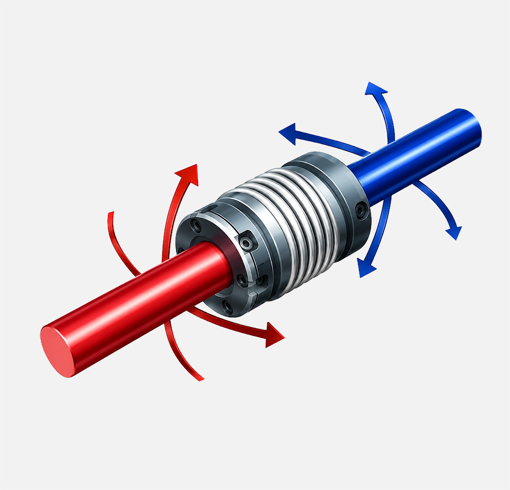
Compensation for angular misalignment between two shafts
ALMA metal bellows couplings connect shafts with high torsional stiffness. They compensate for lateral, angular and axial misalignment.
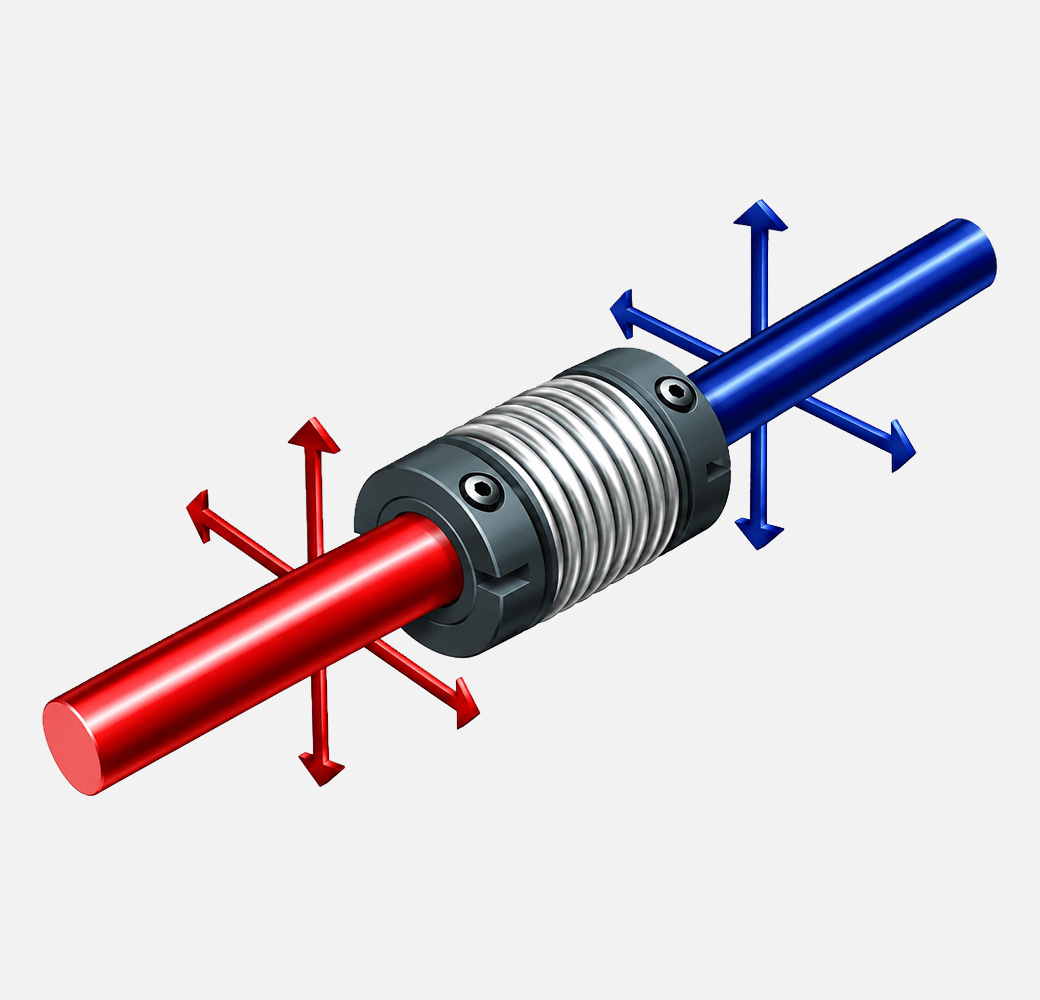
Compensation for parallel misalignment between two shafts
They act as a rigid element in the circumferential direction, enabling torque transmission with high torsional stiffness.
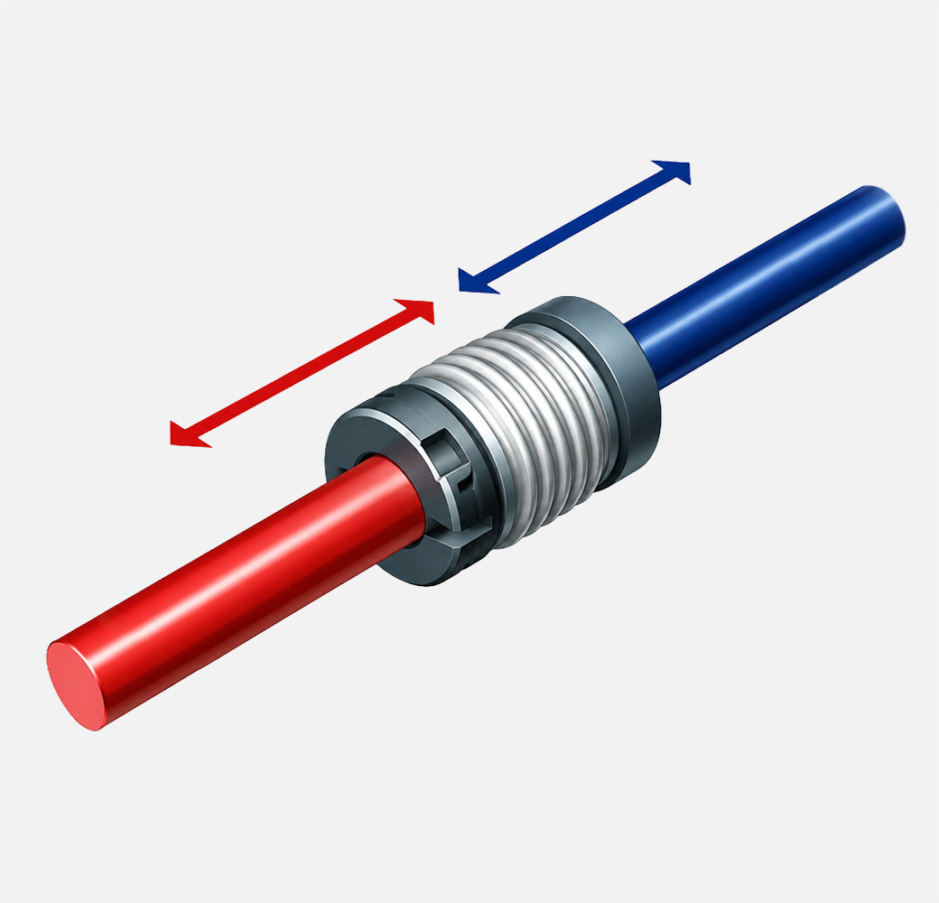
Compensation for axial displacement between two shafts
Metal bellows couplings minimise bearing loads caused by shaft misalignment, helping to extend bearing service life.
The Most Common Applications
Sample positioning in x-y-z-θ, wobble sticks and transfer rods.
Coupling to magnetically coupled or differentially pumped rotary feedthroughs.
Substrate turntables, sputtering and PVD chambers requiring uniform rotation.
Wafer handling, load-lock drives and robotic axes under cleanroom conditions.
Monochromators, apertures and goniometers with exceptionally high angular resolution.
UHV chambers, cryostats and fusion experiments involving bake-out cycles.
Your Benefits:
Measurable precision: Backlash-free transmission maintains repeatability over thousands of cycles.
Fewer failures in vacuum: Reduced transverse forces extend the service life of bearings and rotary feedthroughs.
No wear debris, no contamination: All-metal construction without lubricants prevents lubricant-related contamination and outgassing.
Suitable for bake-out and radiation exposure: The metal bellows withstands high temperatures and ionising radiation within its specified operating limits.
Allowance for assembly tolerances: Misalignment compensation reduces manufacturing and alignment effort.
Compact and lightweight: A low mass moment of inertia improves axis dynamics.
Correct Installation:
Clean: Remove grease and particles from the shafts, bores and coupling; wear gloves.
Align: Align the shafts carefully – the bellows accommodates residual misalignment but does not replace proper alignment.
Slide into place: Slide the coupling onto the shafts without introducing stress. Never force it into place or strike the bellows.
Insertion depth: Engage the full hub length and keep the bellows in its neutral axial position.
Tightening torque: Tighten the clamping screws in a crosswise sequence using a torque wrench, following the manufacturer’s specifications.
Trial run: Before evacuation, rotate slowly and check for runout and unusual noise, then close the chamber.
Materials for Vacuum Applications
| Material | Application | Properties / Notes |
|---|---|---|
| Stainless steel 1.4571 / 316Ti | Bellows | Standard material for HV and UHV, good weldability, corrosion-resistant, suitable for bake-out |
| Stainless steel 1.4404 / 316L / 316Ti | Hubs & bellows | Low magnetic permeability, preferred for magnetically sensitive assemblies |
| Hastelloy / Inconel | Bellows | For higher temperatures, aggressive media and high numbers of load cycles |
| Aluminium | Hubs (external) | Suitable only on the atmospheric side; potentially problematic in UHV due to strength and oxide layer considerations. |
| Avoid in vacuum | – | Elastomers, plastics, lubricated keyed connections, zinc-plated or nickel-plated parts. |